
High-frequency PCB board refers to a printed circuit board with a frequency above 1GHz. This definition may be different in the industry. Its physical properties, accuracy, and technical parameters are very demanding, and it is often used in communication systems, automotive ADAS systems, satellite communication systems, radio systems and other fields.
What is the difference between high-frequency PCB boards and ordinary PCB boards?
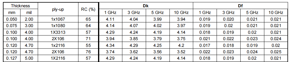
The production process of high-frequency PCB boards is basically the same as that of ordinary PCB boards. The key point to achieve high frequency and high speed lies in the properties of raw materials, that is, the characteristic parameters of raw materials. The main material of high-frequency PCB board is high-frequency copper-clad laminate, and its core requirement is to have low dielectric constant (Dk) and low dielectric loss factor (Df). In addition to ensuring lower Dk and Df, the consistency of Dk parameters is also one of the important factors in measuring the quality of PCB boards. In addition, another important parameter is the impedance characteristics of the PCB board and other physical characteristics.
Several characteristics of high-frequency PCB substrates
The dielectric constant (Dk) of the high-frequency circuit board substrate must be small and stable. Generally speaking, the smaller the better. The signal transmission rate is inversely proportional to the square root of the material’s dielectric constant. A high dielectric constant can easily cause signal transmission delays. .
The dielectric loss (Df) of high-frequency circuit board substrate materials must be small, which mainly affects the quality of signal transmission. The smaller the dielectric loss, the smaller the signal loss.
The impedance of high-frequency circuit boards actually refers to the parameters of resistance and reactance. Impedance control is the most basic principle for our high-speed design, because PCB lines must consider the insertion and installation of electronic components, and consider the conductive performance and signal transmission after insertion. Performance and other issues, so the lower the impedance, the better. Generally, major board manufacturers will ensure a certain degree of impedance error during PCB processing.
The base material of high-frequency circuit boards should have low water absorption. High water absorption will cause dielectric constant and dielectric loss when it gets wet.
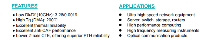
High frequency material properties
Compared with high-speed materials, high-frequency materials pay more attention to the size and change of the material's dielectric constant (Dk). High frequency products are very sensitive to changes in the material's dielectric constant (Dk). Therefore, the focus of high-frequency materials is the stability of the dielectric constant (Dk), as well as the material dielectric thickness, the temperature drift coefficient of the material, and the stroboscopic performance of the material. There is no clear classification standard for high-frequency materials in the industry, but many PCB manufacturers roughly classify high-frequency boards based on the dielectric constant (Dk) of the material. Materials with the same dielectric constant (Dk) are considered similar and can be substituted for each other.
There is also a commonly used division method in the field of high-frequency materials, which is to divide materials into PTFE materials and non-PTFE materials. This is closely related to the application fields of high-frequency products. The current radio frequency field can be divided into two parts. First, the commonly used frequencies below 6GHZ are 3.5GHZ, 2.7GHZ, and 1.8GHZ. The main products are power amplifiers, antenna calibrators, arrays and other products. The other part is that the commonly used frequencies in the millimeter wave field above 20GHZ are 24GHZ, 66GHZ, and 77GHZ, and the main products are radar products. This is mainly because as the frequency increases, the stroboscopic effect and dielectric loss of non-PTFE products have a sharp increase in the impact on signal transmission, while PTFE materials have better performance characteristics.
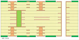
The stackup of a high-frequency PCB typically exhibits characteristics that prioritize controlled impedance and minimize signal losses
Key features include a symmetrical layer arrangement, dedicated ground planes, and the use of low-loss dielectric materials such as PTFE. Controlled impedance traces and impedance matching techniques are commonly employed to ensure signal integrity and minimize reflections. Additionally, careful consideration is given to reduce electromagnetic interference (EMI) and crosstalk, often involving the incorporation of shielding layers. Overall, the stackup design aims to provide consistent and reliable signal performance at high frequencies.
Traditional copper-clad laminate materials have large transmission losses and cannot meet the requirements for high-frequency signal transmission quality. Therefore, the most important performance of PCB substrate materials used in 5G communications is to meet the requirements of high frequency and high speed, as well as the requirements of integration, miniaturization, lightweight, multi-function and high reliability. In particular, resin materials require low dielectric constant (Dk), low dielectric loss (Df), low coefficient of thermal expansion (CTE) and high thermal conductivity. Currently, rigid copper-clad laminates, represented by polytetrafluoroethylene (PTFE) thermoplastic materials and hydrocarbon resin (PCH) thermosetting materials, account for the vast majority of high-frequency/high-speed PCB substrates due to their unparalleled low dielectric properties. market. In recent years, polyphenylene ether (PPO or PPE), bismaleimide (BMI), cyanate ester (CE), triazine resin (BT), benzoxazine (BOZ) and benzocyclobutene ( BCB) and related modifications and other new resin materials for high-frequency/high-speed PCB substrates.
Polyphenylene ether (PPO or PPE), distinguished by dielectric properties surpassed only by PTFE, has emerged as a material of significant industry interest in recent years. Moreover, the processability of PPO materials exceeds that of PTFE, rendering modified PPO resin, such as Panasonic M6, M7N, and Lianmao's IT968, IT988GSE, the preferred choice for achieving very low loss (Very Low Loss) and ultra low loss (Ultra Low Loss) in high-speed boards. The resin system employed in high-frequency boards predominantly features polytetrafluoroethylene (PTFE) thermoplastic material and hydrocarbon resin (PCH). Despite the ability to attain exceptionally low dielectric loss (Df) and a stable dielectric constant (Dk), the poor processability of the material renders it unsuitable for high-multilayer boards and, particularly, for HDI board processing.
The advent of 5G communications has propelled an escalation in the complexity of high-frequency product PCBs, transcending traditional single- and double-sided structures to encompass multi-layer boards, even with HDI design specifications. Material developers have responded by integrating PPO resin into high-frequency boards, ensuring both extremely low dielectric loss (Df) and stable dielectric constant (Dk), while concurrently enhancing the material's PCB processability. Exemplifying this approach, Lianmao's IT-88GMW, IT-8300GA, IT-8350G, IT-8338G, IT-8615G, and other high-frequency plates employ a hybrid system comprising modified PPO resin and hydrocarbon resin. This strategic formulation not only meets the demands of high-frequency signal transmission but also significantly augments material processability.
The dual trajectory of 5G development—towards higher speeds and frequencies, necessitates a commensurate reduction in material dielectric loss (Df) and dielectric constant (Dk). Simultaneously, the imperative for 5G products to be more compact and uniform compels corresponding PCBs to advance towards higher multi-layer configurations, potentially even incorporating HDI specifications. In this context, the utilization of polyphenylene ether (PPO or PPE) resin emerges as an auspicious development direction, resonating with the evolving requirements of both high-frequency and high-speed materials.
Post time: Dec-09-2023


